A Numerical Study on the Characteristics of a Thick Flapped Rudder depending on Various Geometric Parameters using Computational Fluid Dynamics Technique
Article information
Abstract
A marine flapped rudder is designed to improve the effective lift generated by the rudder; this also improves the maneuverability of the ship. The flap is a high lift device installed at the trailing edge of the rudder to augment lift. In this paper, the characteristics of a thick flapped rudder are analyzed at a low Reynolds number with various ratios of flap chord length to total chord length and various aspect ratios, based on the computational fluid dynamics technique. The performance of the rudder with respect to lift, drag, and center of pressure are investigated, and the efficient ratio of flap chord length to total chord length and improved aspect ratio are determined. Ed: highlight – or ‘superior’. As a case study, the flow on the flapped rudder of an NACA0021 section shape in free stream condition is simulated. The standard k-epsilon turbulence model is used to model the flow around the flapped rudder. The results indicate that the efficient ratio of the flap chord length to total chord length and aspect ratio are 0.3 and 1.4, respectively.
1. Introduction
Energy Efficiency Design Index (EEDI) regulations have been introduced to the International Convention for the Prevention of Pollution from Ships (MARPOL) in recent years to improve energy efficiency of ships and reduce emission due to shipping operations (Shigunov and Papanikolaou, 2015). Following these regulations, ships are required to reduce installed power but still ensure maneuverability under both normal and adverse condition. Meanwhile, fuel consumption of the ship greatly depends on its resistance which may be reduced by adopting small area rudder. The solution to improve energy efficiency is not only by simply reducing the rudder area but also by using high efficient equipment for propulsion of a ship.
Regarding steering devices, flapped rudders are known to be relatively easy to install while allowing for the lowest possible fuel consumption with small size of steering gear. Since the rudder can significantly increase the lift, it can be applied to situation when space is limited.
The concept of flapped rudders was first proposed by Lumley. Kato and Motora(1968) carried out the first systematic sets of open water tests on NACA 0020 flapped rudders. Kerwin et al. (1972) carried out free-stream tests on a series of twelve flapped rudders in the water tunnel. Their experiments show that the maximum lift coefficients of flapped rudder at low Reynolds number and high Reynolds number increase up to 45 % and 75 %, respectively. In addition, the flapped rudder with thin profile is better than the thick one due to the lower drag (Molland and Turnock, 2007). On the other hand, it is proved that Coanda devices can be applied to a rudder with thick profile to improve both lift and drag performances (Ahn and Kim, 1999; Seo and Lee, 2013).
For these reasons, the objective of this paper is to investigate hydrodynamic characteristics of a thick flapped rudder using RANS CFD analysis. The flapped rudder with various ratio of flap chord length to total chord length and various aspect ratios are simulated in free stream condition, and hydrodynamic characteristics of such rudders are investigated. The best hydrodynamic performance of the rudder is predicted, and then the efficient ratio of flap chord length to total chord length and the better aspect ratio are determined.
2. Background
2.1. Characteristics of the flapped rudder
The flapped rudder is created by modifying a standard rudder to induce bigger lift. The rudder consists of two or more sections, which move relative to each other. Fig. 1 shows the geometric definition of the flapped rudder used in this paper, and Fig. 2 shows the force diagram of the flapped rudder.

Geometric definition of a flapped rudder
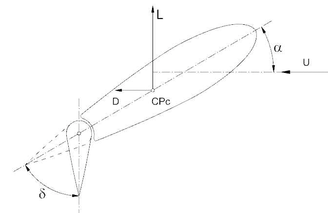
Force diagram of the flapped rudder.
The definitions of hydrodynamic coefficients of the flapped rudder are given by
The Reynolds number and aspect ratio is defined as follows;
where, U, L, D, ρ, ν, A, S, c, cf, α, δ, AR, CPc, Re, CL, and CD are the inflow velocity to the rudder, lift, drag, water density, kinematic viscosity of water, rudder area, height of the rudder, total chord length, flap chord length, rudder angle, flap angle, aspect ratio, center of pressure from the leading edge, Reynolds number, lift coefficient, and drag coefficient, respectively.
2.2. Calculation method
This paper uses the Reynolds-Averaged Navier Stokes (RANS) approach to simulate the fluid flow around the flapped rudder. The approach applies the Reynolds decomposition technique that breaks the velocity down into its mean and fluctuating components. The decomposition leaves one unknown value, which is termed as the Reynolds Stress. Turbulence models are then used to resolve the Reynolds’s Stress, and close the equation set.
There are several turbulence models and the k-ε turbulence model is known as the most widely-used engineering one for industrial application. Hence, the standard k-ε turbulence model is adopted to simulate fluid flow around the flapped rudder.
3. Numerical Calculation
3.1. Case study
The simulation is performed for the flapped rudder of common profile shape NACA0021 with each case of ratio of flap chord length to total chord length of 0.2, 0.3, 0.4, and 0.5, and the aspect ratio of 1.3, 1.4, 1.5, and 1.6 for angles of attack at 0, 10, 15, 20, 25, 30, and 35 degrees. Thua and Yoon(2016) concluded that the efficient ratio of flap angle to rudder angle is 2, so the flap angle is twice of the rudder angle. Table 1 lists the main parameters of the flapped rudder model. Table 2.

Main parameters of the flapped rudder model

Fluid properties
3.2. Computation process
In this paper, the effect of variation in the ratios of flap chord length to total chord length and aspect ratios on hydrodynamic characteristics of flapped rudder is analyzed by using ANSYS FLUENT code. The methodology for computation involves geometry modeling, meshing generation, problem solving, and post-processing. The 3D geometry of the flapped rudder is created from 2D coordinates of the NACA0021 profile.
A fluid domain covering the rudder is then generated. The fluid domain should be large enough to obtain convergence conditions of flow at inlet and outlet as well as avoiding effect of walls on inflow to the rudder surface. The flapped rudder model is simulated in the fluid domain with length of 10c, breadth of 8c, and height of 4h as shown in Fig. 3. Tetrahedral finite volumes are chosen to generate mesh of the complete domain. A smooth progression in cell size is applied to the area of gap between main rudder and flap. The fluid domain is discretized by approximate 4 million elements. Mesh on the fluid domain and the rudder surface are shown in Fig. 3. Minimum skewness mesh quality is 0.21.
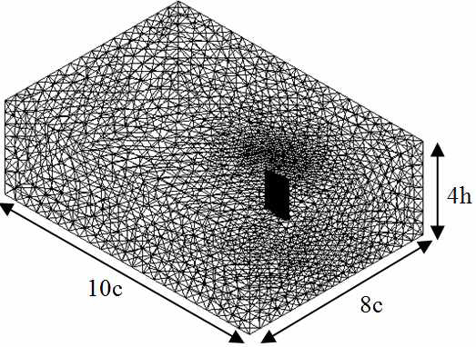
Fluid domain and meshing
The boundaries of top, bottom, and side walls are set as slip wall. The inlet boundary has uniform velocity while the outlet boundary has pressure outlet. No-slip wall is set for the rudder surface. Those boundary conditions are summarized in Table 3. Converged results are obtained after the scaled continuity residuals were found to be less than 1.0E-4 and the scaled energy residual decrease to 1.0E-6.

Boundary conditions
The turbulence model of standard k-ε is used for modeling flow through the flapped rudder. Numerical models are summarized in Table 4.

Numerical models
4. Results and analysis
4.1. Verification of simulation model
The results obtained from the simulation of all movable NACA0021 rudder at Reynolds number of 0.28E+6 are compared to the experimental results with similar geometric parameters and the same Reynolds Number performed in the towing tank(Ahn and Kim, 1999). It is found that simulation values are in good agreement with experimental values as shown in Fig. 4. As a consequence, the model is presumed to be useful to investigate hydrodynamic characteristics of the flapped rudder of NACA0021 profile.
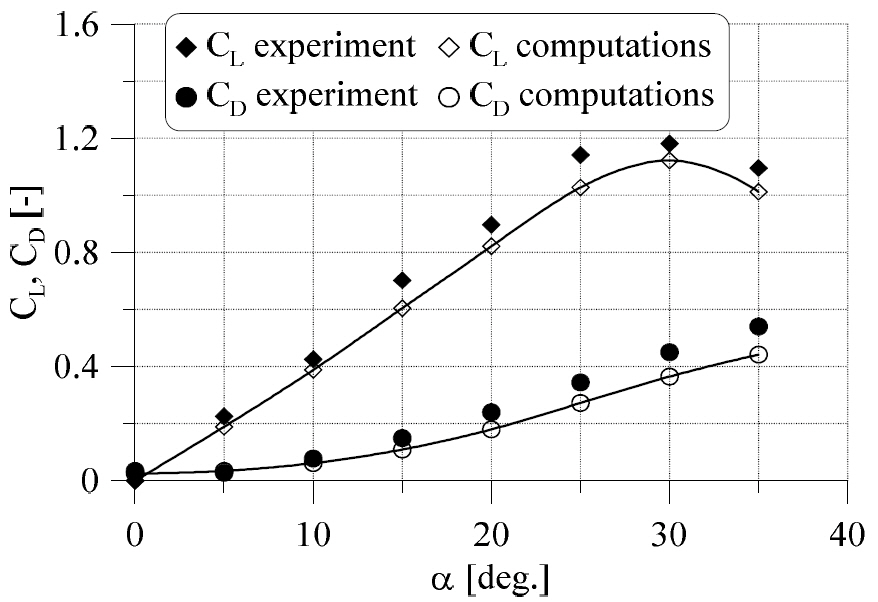
Comparison between experimental results and simulation results for all movable NACA0021 rudder
4.2. Effect of variation of flap length ratio
Figs. 5~7 show the characteristics of the NACA0021 flapped rudder for ratios of flap chord length to rudder chord length of 0.2, 0.3, 0.4, and 0.5. All four ratios give significant increases in the lift. However, there are decreases in both maximum lift coefficient and stall angle as the flap length ratio increases, especially in the cases of flap length ratios of 0.4 and 0.5.
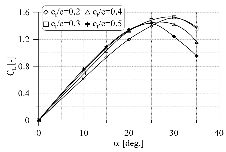
Lift coefficient with variation of the flap chord

Center of pressure for various flap chord lengths
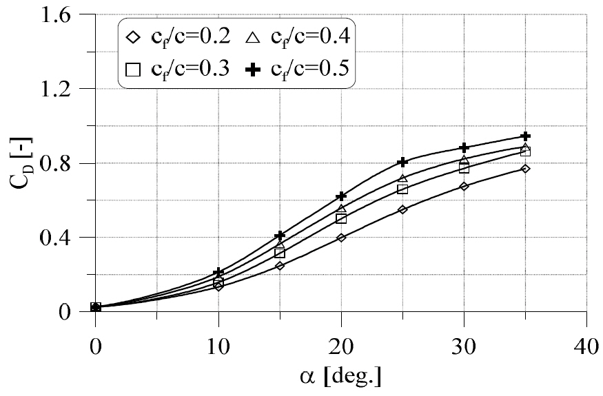
Drag coefficient with variation of the flap chord length ratio
The drag coefficient also increases with increasing the flap length ratio. The increase of flap chord length could result in increasing flap area as well as high pressure on the flap surface, which lead to augmentation of both lift and drag.
The center of pressure from the leading edge tends to move forward as the angle of attack becomes small. The center of pressure then moves towards the leading edge, reaching its shortest position from the leading edge around the stall angle. It is rather great when the angle of attack is greater than the stall angle.
Figs. 8~9 show the velocity vectors and pressure distributions depending on the change of flap length ratio. As shown in Fig. 8, the flow separation occurs a little earlier at high angle of attack when the flap length ratio is 0.5.
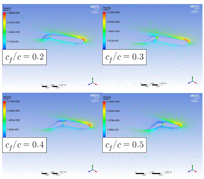
Velocity vectors at the middle section of the flapped rudder and angle of attack of 30 degrees
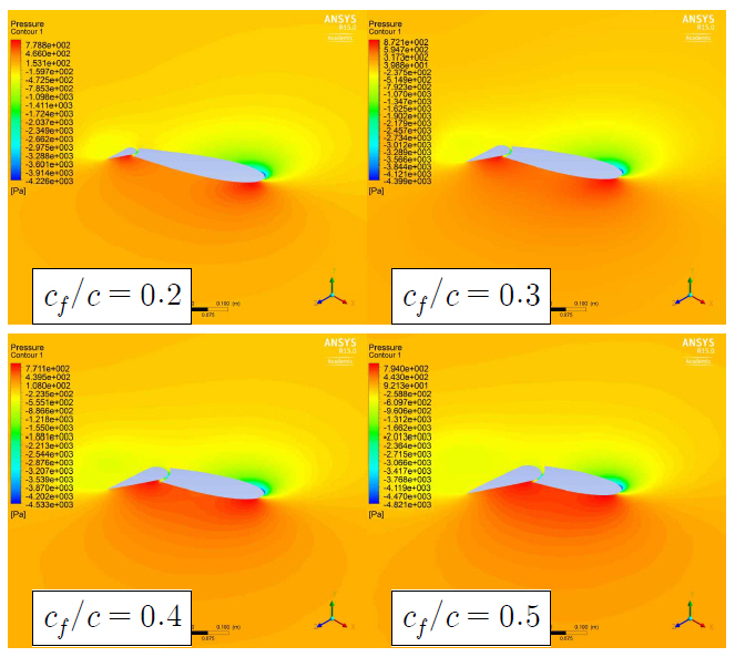
Pressure contours at the middle section of the flapped rudder and angle of attack of 25 degrees
4.3. Effect of variation in aspect ratio
Figs. 10~12 show the calculation results of the lift, drag, and center of pressure of the flapped rudder of various aspect ratio with a view to determine the relation between aspect ratios and flapped rudder characteristics.
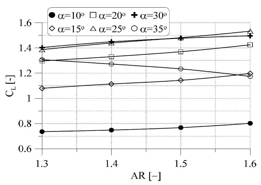
Lift coefficient for variation in aspect ratio

Center of pressure for variation in aspect ratio

Drag coefficient for variation in aspect ratio.
The lift coefficient increases with increase in aspect ratio except a large angle of attack case, while the drag has a relatively small change. The center of pressure from the leading edge tends to move towards the leading edge for aspect ratio increasing from 1.3 to 1.4. And then it moves to the trailing edge, and reaches its most backward position in the case of aspect ratio of 1.5. It may be explained that the strongest vortex flow on the back face of flap and the highest pressure on the pressure face induce the greatest lift of flap for aspect ratio of 1.5.
Fig. 13 shows the streamlines at an attack angle of 30 degrees. Fig. 14 depicts pressure contours on the pressure face at the same angle of attack. Since the aspect ratio is limited by the clearance of stern of a ship, a small aspect ratio is more desirable than the large one.
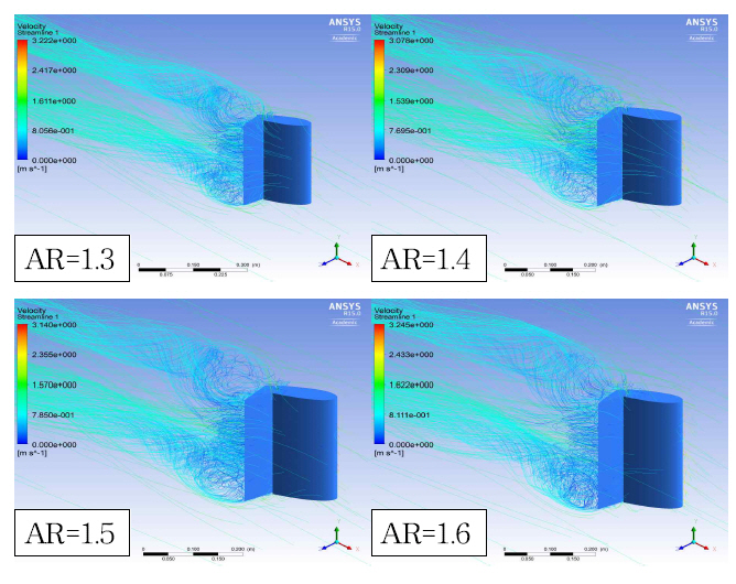
Streamlines at an angle of attack of 30 degrees
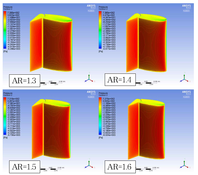
Pressure contours on pressure face at an attack angle of 30 degrees
If there is not dramatical increase in the lift, it is advantageous that the center of pressure is close to the leading edge in the viewpoint of decreasing rudder torque. As we have already said, low aspect ratio is recommended in the condition of the similar lift-drag ratio. For this reason, it is found that the better aspect ratio is 1.4.
5. Conclusion
This paper analyzed the performance of thick flapped rudder at low Reynolds number by varying ratios of flap chord length to total chord length and aspect ratio, based on RANS approach. Computations were performed for a flapped rudder of NACA0021 section with ratios of the flap chord length of 0.2, 0.3, 0.4, and 0.5, and the aspect ratio of 1.3, 1.4, 1.5, and 1.6. The lift, drag, and center of pressure from the leading edge were obtained and the flow characteristics of the rudder were investigated.
The most efficient ratio of flap chord length to total chord length is 0.3. where it was concluded that the achieved lift coefficients at 10, 20, and 30 degrees are 62.3 %, 47.6 %, and 29.5 % higher, respectively, than those of the ordinary rudder. The aspect ratio makes significant effect on lift but drag. High aspect ratio results in high lift. When the aspect ratio increases, the center of pressure moves to the trailing edge. So, 1.4 of aspect ratio is suggested in the viewpoint of decreasing the rudder torque.
Acknowledgements
This research was supported by “Development of Solution for Safety and Optimal Navigation Path of a Ship Considering the Sea State” sponsored by Korean Evaluation Institute of Industrial Technology, “KEIT”.